James W. Heffel
University of California,
Riverside, CE-CERT
Douglas C. Johnson
Cal-Draulics
Carroll Shelby
Carroll Shelby Enterprises
(re-published
2003 by permission)
ABSTRACT
This paper describes the details of converting a gasoline
powered 427 Shelby Cobra to run on gaseous hydrogen. The purpose of this
project was to design a vehicle capable of beating the current land speed
record for hydrogen powered vehicles.
The vehicle uses a modified 427 Ford FE engine as the power
plant with a specially designed electronic fuel injection system for metering
the hydrogen. The engine was designed to produce near zero emissions (<10
ppm NOx) at approximately 270 HP using a lean burn, “quality controlled”,
fueling strategy (no pollution control devices are utilized).
INTRODUCTION
In the early 1990’s, a long time hydrogen advocate named
Ben Jordan built a trophy to be given each year to the fastest hydrogen
powered vehicle. The competition is held at the Bonneville Salt Flats in Utah.
The current record for this competition is 108.268 mph held by AHA member,
Terry Young of Middle Tennessee State University. Since there is currently no
official class for hydrogen fueled vehicles, the vehicles are run in what is
called a “time only” category 1). The goal was to build a vehicle capable
of beating that record and win the Ben Jordan trophy
BACKGROUND
Hydrogen is widely regarded as a promising transportation
fuel because it is clean, abundant, and renewable. In a gaseous state, it is
colorless, odorless, and non-toxic. When hydrogen is combusted with oxygen, it
forms water as the by-product. Due to hydrogen’s high flammability range, it
can be completely combusted over a wide range of air/fuel ratios. Unlike
gasoline, which if combusted outside its optimal air/fuel ratio will produce
excess carbon monoxide (CO) and hydrocarbons (HC), hydrogen does not have a
carbon element and therefore will not produce those toxic gases. Like gasoline
however, when hydrogen is combusted in air (mixture of oxygen and nitrogen)
the temperature of combustion can cause the formation of the nitric oxidizes (NOx).
Hydrogen however has an advantage over gasoline in this area because it can be
combusted using very high air/fuel ratios. Using a high air/fuel ratio (i.e.
combusting hydrogen with more air than is theoretically required) causes the
combustion temperature to drop dramatically and thus causes a reduction in the
formation of NOx. Unfortunately, the use of excess air also lowers the power
output of the engine. [1]
Over the past eight years, the University of
California – Riverside, College of Engineering – Center for Environmental
Research and Technology (CE CERT) has been experimenting with improving the
performance of hydrogen-powered vehicles. Most of these methods have involved
using superchargers [2] and turbochargers [3] to bring up the power. While
these devices have worked to some degree, it was felt these methods were too
complicated of a solution to a simple problem. The authors of this paper
believed the simple solution was to just make the engine bigger. Or use a car
that has “way more engine” (Horsepower) than it really needs. The author
of this paper chose the latter - and what better car for this than the Shelby
Cobra?
The Shelby Cobra
The Cobra was the brainchild of racecar driver, Carroll Shelby. In 1962,
Shelby worked a deal with Britain’s AC Cars and America’s Ford Motor
Company to develop the quickest production vehicle in the world. Initially,
street Cobras were powered by stock HiPo 260 Fords, but were soon replaced
with HiPo 289s rated at 271 HP. In January 1963, the Cobra won
its first race at the SCCA divisional race at Riverside
Speedway. The racing legacy of Carroll Shelby’s Cobra had begun. Over the
next few years, the 289 Cobra dominated the racing circuit. In January 1965,
Shelby started the production of the 427 Cobra, which used a Ford 427 side-oiler.
Although, the 289 was by far the biggest winner, whatever the 289 did, the 427
did better. The 427 Cobra was and remains the “world’s quickest production
car”. That was proven with 0 – 60 mph times of 3.8 seconds, 0 – 100 mph
in 10.6 seconds, and 0 – 100 and back to a dead stop in less than 14
seconds. [4]
In 1996 Shelby American, Inc. announced the reintroduction
of the Shelby 427 S/C Cobra as the CSX4000 component vehicle. The cars are
sold as “rollers” (less the engine and transmission).
In a chance meeting with Carroll Shelby, James Heffel
discussed the proposed project with Carroll and with little hesitation; agreed
to provide one of his new Cobras for this project.
VEHICLE CONVERSION
The Cobra roller (Vehicle Serial Number CSX 4201) was picked up from Shelby
America, Inc. in Las Vegas, Nevada and the engine (an all aluminum 427 cubic
inches replica of the original Ford FE side-oiler) was picked up from Shelby’s
facility in Gardena, California on August 19, 2000.

Figure 1 – Picture of car as delivered
(no paint engine or transmission)
The car and engine were delivered to Cal-Draulics of
Corona, California, where the hydrogen conversion was to be conducted. The
project was broken down into the following five tasks:
Task 1. Set up the car to run on gasoline.
Task 2. Paint the car.
Task 3. Install the roll cage and fire suppression system
Task 4. Do a car and driver checkout run (on gasoline) at El Mirage Dry Lake
Bed.
Task 5. Convert the car to run on hydrogen.
Task 6. Do a record attempt at Bonneville Salt Flats (Oct. 2000).
With limited funds and limited time, the following set of conditions were
developed:
1. Do it as simple as possible
2. Do it as quickly as possible
3. Do it as economically as possible (and still beat the
record)
Tasks 1, 2, and 3
The first order of business was to get the engine and
transmission mated together and then installed this assembly into the car.
Instead of the using a 4-speed “top loader” transmission originally used
in the 1965 Cobras, a 5-speed Tremec TKO manual transmission was chosen. To
comply with the Bonneville National rules, a steel shatter shield was required
in place of the aluminum bellhousing. For this, a shatter shield made by
Lakewood was used. To mate the shatter shield to the transmission, an adaptor
plate, made by McLeod, was used. A Centerforce, double acting clutch and
flywheel were employed to provide positive engagement between the engine and
transmission. Wayne’s Engine Rebuilding, Inc. of Riverside, California,
balanced the clutch, disc, and flywheel. The clutch fork and throw out
bearing, normally used on 1970 Ford Broncos, was utilized to finalize the
transmission assembly.
To ease the installation of the transmission/engine, the
radiator was removed and the engine/transmission assembly was carefully
lowered into the car as a single unit. The transmission was secured to the
chassis using a transmission mount (new) from a late model Ford Mustang and
the engine was secured to the chassis using motor mounts from a 1965 Ford
Galaxy Station Wagon (also new). To connect the output shaft of the
transmission to the input shaft of the Dana 44 differential, Golden State Axle
of Corona, California fabricated a special 13-inch long driveshaft.
Following the installation of the engine and transmission, the car was sent
to the paint shop where Tony Avila, Tony, Jr. and Herman Broom gave it the
flashy red paint job with two white racing stripes
down the center. Tony, Herman, and Tony, Jr. also assisted
in the installation of the hydrogen storage tank. From the paint shop the car
went back to Cal Draulics where a small gasoline tank was installed in the
trunk of the car so it could be tested on gasoline to verify all the
components (engine, transmission, clutch, brakes, etc) were operating
properly. Once this was completed, the car went to Cook Motorsports in Norco,
California, where the installation of the roll cage and fire suppression
system was conducted. All these tasks were completed by October 7, 2000.
Task 4
On October 8, the car was taken to El Mirage Dry Lake Bed
in the high desert of California to do a test run on gasoline. A speed of 135
mph was recorded with James Heffel driving. This was not a maximum speed run.
This run was performed to verify that both the car and the driver were capable
of operating at speeds above the current hydrogen record, prior to attempting
this using hydrogen.
Task 5
Hydrogen Fuel Injection System
One of the primary problems encountered in the development
of operational hydrogen engines is pr mature ignition (pre-ignition). Pre
-ignition occurs when the cylinder charge becomes ignited before the ignition
by the spark plug. If this condition occurs when the intake valve is open, the
flame can travel back into the induction system. Various fuel injection
methods have been experimented with over the years. These methods have
included carbureted systems, which mix the air and fuel at a central point
upstream of the intake valves; port injection systems that inject the fuel
into the air stream near the intake valve; and direct injection systems that
inject the fuel directly into the combustion chamber. For carburetor-type
systems, which can have a substantial amount of air and fuel in the manifold,
pre-ignition can have a devastating effect. Port injection systems, which tend
to have less fuel in the manifold at any one time, can minimize this effect.
Running lean (excess air) and precisely timing the injector opening and
closing times (tuning the system), can virtually eliminate pre-ignition from
occurring. Direct injection system can eliminate pre-ignition in the intake
manifold, however it does not necessarily eliminate it in the combustion
chamber. Direct injection systems also require higher fuel pressure and tend
to be a little more complicated than the other two methods. The method that
was chosen for this project was the port injection system. The fuel injectors
used to meter the fuel are solenoid operated, pulse-width modulated, sonic
flow injectors especially designed for gaseous fuels. These injectors were
provided by IMPCO Technologies, Inc. of Irvine, California. A cross-section
view of this injector is shown in Figure 2.
Figure 2 – Cross-section of injector
Numerous design options were considered with regard to the
fuel injection system. Knowing little time was available to fine-tune the
system (and thus totally eliminating the possibility of pre-ignition), we
chose a design that would be somewhat tolerant to an occasional pre-ignition
event. This design involved replacing the existing intake manifold (made for a
four-barrel carburetor), with an intake manifold designed to use four 2-barrel
Weber carburetors.
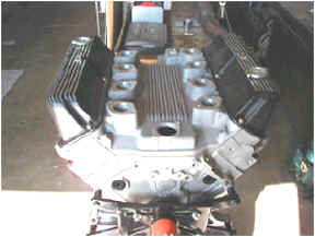
Figure 3 – Intake Manifold
This new manifold provided short, single runners for each cylinder. For
each runner, a 1 ½ inch tall injector body was designed and fabricated to
house the injectors.
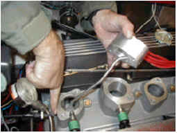
Figure 4 - Injector body
Each injector body was designed to incorporate a ¼ inch
tube that transported the hydrogen from the injector outlet to within an inch
of the intake valve. This was to minimize the amount of hydrogen that would be
in contact with the air in the runner. That way if pre-ignition was to occur,
damage to the intake system would negligible.
Additionally, a “quality” control fuel strategy was
selected as the basis for metering the hydrogen. A distinct advantage of using
hydrogen as a fuel, with its wide range of flammability, is the fuel-to-air
ratio or the “quality” of the charge mixture can easily be varied to meet
different driving conditions or loads. This is similar to the strategy used by
diesel engines. In contrast, for a gasoline engine, the fuel-to-air ratio must
be kept more or less constant throughout the driving range. In other words,
the “quantity” of the charge is controlled. Using a “quality”
controlled strategy enables the engine to operate at a constant
wide-open-throttle (WOT) position throughout the power band (just add more
fuel for more torque). To communicate to the Engine Control Computer (ECC) the
amount of fuel desired, a throttle position indicator was connected to the gas
pedal (not to the throttle plates since they are normally at WOT). Basically
the gas pedal acted as an electronic sensor that would send a fuel demand
signal to the ECC. The ECC would base how long it would hold an injector open
on this signal.
To facilitate the starting of the engine, a choke
(butterfly valve) was designed and fabricated for each injector body.
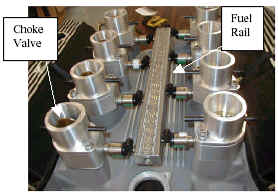
Figure 5 – Choke Assembly and Fuel Rail
All eight chokes are linked together and centrally controlled by a
hand-operated cable located in the cockpit of the vehicle. Once the engine
started, the chokes are pulled to the wide-open position and the “quality”
controlled fuel metering strategy is implemented.
Since the design of this system allows the flow of hydrogen and air to each
cylinder to be independent of each other, any occurrence of pre-ignition in
one cylinder would not influence (ignite) the air/fuel mixture of another.
Whereas with systems that manifold all the intake runners together, a
pre-ignition in one cylinder can light the whole intake manifold on fire. To
maximize the airflow to engine, each manifold runner, intake port, injector
body and throttle body
were match-ported. See Figure 6.
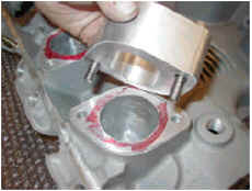
Figure 6– Match porting injector with intake manifold
To supply fuel to each injector, a single fuel rail was
designed and fabricated. See Figure 5. This fuel rail contains a port for each
of the fuel injectors.
Hydrogen Storage
The hydrogen storage tank was provided by IMPCO
Technologies,
Inc. of Irvine, California.
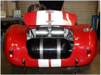
Figure 7 – Hydrogen storage tank
The tank has a Type IV rating and uses a plastic bladder
wrapped with high strength composite graphite. The tank has a water volume of
87 liters and is rated up to 3,600 psi. At 3,600 psi, the tank holds 590 SCF
of hydrogen, which is equivalent to 1.4 gallons of gasoline. At 200 HP, this
tank is emptied in about 5 minutes.
Hydrogen Ancillary System
The hydrogen ancillary system consists of a high flow
capacity pressure regulator, a manual shut-off valve, a solenoid operated “on/off’
valve, three pressure gauges and a fuel line. The pressure regulator, provided
by Control Seal Controls, is used to reduce the pressure of the fuel in the
storage tank (3600 psi) to a useable fuel rail pressure of 100 psi. Upstream
of this valve is a manually operated ball valve and pressure gauge. A
quarter-turn of this valve will shut off the hydrogen in the event of a leak
or fire. The pressure gauge reads the pressure of the fuel in the storage
tank. Downstream of the pressure regulator is a solenoid-operated valve and a
second pressure gauge. The solenoid valve is controlled via a switch mounted
in the cockpit of the vehicle. This valve is a “normally closed” valve,
meaning in the event of a power failure this valve will automatically close.
This pressure gauge reads the pressure at the outlet of the pressure
regulator. The third pressure gauge is located at the engine fuel rail and
reads fuel pressure at the engine.
The Engine
The engine used for this car is an all aluminum replica of
the original 427 Ford side-oiler. Even though this powerful engine would have
met the needs of the project, it was decided to bore and stroke it to 526
cubic inches (4.375” x 4.375”) and give it a 12:1 compression ratio This
engine was dynamometer tested by Mike LeFevers at 600HP (at 6,100 rpm) using
gasoline.
Performance
The theoretical maximum power output from a hydrogen engine
depends on the fuel injection method used. This is because hydrogen will
displace a large portion of the incoming air, and thus limiting the amount of
air that will enter the combustion chamber. For example, the stoichiometric
air/fuel ratio for hydrogen 34:1. For this mixture, hydrogen will displace 29%
of the combustion chamber, leaving only 71% for the air. As a result, the
energy content of this mixture will be 15% less than it would be if the fuel
were gasoline (since gasoline is a liquid, it only occupies a very small
volume of the combustion chamber, and thus allows more air to enter). Since
both the carbureted and port injection methods mix the fuel and air prior to
it entering the combustion chamber, these systems limit the maximum power
obtainable to 85%
of that of gasoline engines (rough order of magnitude). For direct
injection systems, which mix the fuel with the air after the intake valve has
closed (and thus the combustion chamber has 100% air), the maximum output of
the engine can be 15% higher than that for gasoline engines (again, rough
order of magnitude).
Therefore, depending on how the fuel is metered, the
maximum output for a hydrogen engine can be either 15% higher or 15% less than
that of gasoline if a stoichiometric air/fuel ratio is used. However, at a
stoichiometric air/fuel ratio, the combustion temperature is very high and as
a result it will form a large amount of nitric oxides (NOx), which is a
criteria pollutant. Since one of the reasons for using hydrogen is low exhaust
emissions, hydrogen engines are not normally designed to run at a
stoichiometric air/fuel ratio.
Shown in Figure 8 is a plot of NOx formation versus
equivalence ratio phi (equivalence ratio is the actual air/fuel ratio divided
by the stoichiometric air/fuel ratio. If the value for phi is less than one,
the mixture has excess air and therefore is lean. If the value for phi is
greater than one, the mixture has excess fuel and therefore rich).
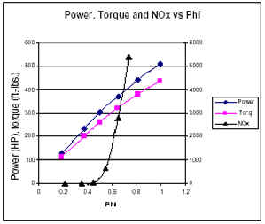
Figure 8 – Power, torque and NOx vs. phi
From this plot is can be seen that in order to keep the NOx
formation low, a phi of 0.45 (A/F of 80:1) or less is required (above a phi of
.45, NOx emissions increase very quickly as the phi increases). Also shown on
this graph is a relationship of power (based on an engine speed of 6,100 rpm)
and torque as phi changes. At a phi equal to 1 (stoichiometric), this engine
would theoretically produce a maximum power and torque of 510 HP and 440
ft-lb, respectively. However at this power output, the engine would be
producing a large amount of NOx emissions. From Figure 8 it can be seen that
the maximum “clean” power (at 6,100 rpm) and torque (i.e. near zero
pollution without any exhaust gas after-treatment or pollution control
devices) would be about 270 HP and 230 ft -lb, respectively. This would occur
at a .45 phi.
Figure 9 – Compression vs. Air/Fuel mixtures
Running at a phi of 0.45 also has other benefits besides reducing NOx
emissions. The first is its “effective octane” rating is increased (i.e.
its ability to operate at higher compression ratio increases). As it can be
seen in Figure 9, hydrogen can tolerate compressions of 15:1 at a 60% lean
mixture (.4 phi). Whereas, at a stoichiometric or a chemically correct mixture
(CCM), it can only tolerate compression ratios slightly above 8:1. Limiting
the maximum fueling rate to a phi of .45 (based on low emissions), the engine
will have a power vs engine speed curve similar to the one shown in Figure 10.
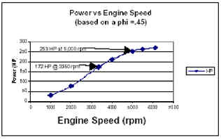
Figure 10 – Power vs Engine Speed (at phi = .45)
Hydrogen’s simple atomic structure along with its ability to burn under
ultra-lean conditions also contributes to a ratio of specific heat closer to
1.4 (ideal gas). Both the compression ratio and the ratio of specific heat are
the two variables in the calculation of thermodynamic efficiency (see equation
1).
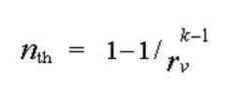
Where rv = the compression
ratio and k = the ratio of specific heats
Equation 1
The higher these values, the higher the thermodynamic efficiency of the
engine. The lean air/fuel mixtures also lower the chances of pre-ignition
occurring
Valve Timing
The camshaft that came with the engine was designed to
produce its maximum power at high engine speeds. It was ground to have 48
degrees of valve overlap and 268 degrees of duration with a 0.74-inch valve
lift at .050-inch tappet lift. This type of grind will typically produce
excellent airflow (high volumetric efficiency) at high engine speeds, at the
expense poor air dynamics at the lower engine speeds. For gasoline fueled
engines, this typically means low efficiencies, poor idle, and high emissions.
For racing purposes, this compromise for high engine speeds is worth it.
Drivetrain
As mentioned earlier, a Tremec TKO 5-speed manual
transmission was installed. This transmission has the following gear ratios:
1 st gear: 3.27:1
2 nd gear: 1.98:1
3 rd gear: 1.34:1
4 th gear: 1:1
5 th gear: .68:1
The Cobra came with a Dana 44 differential with a 3.54:1
gear ratio and a set of B. F. Goodrich P295/50R15 rear tires that have a
26.1-inch diameter. Figure 11 shows a plot of the vehicle speed versus engine
speed for this drivetrain.
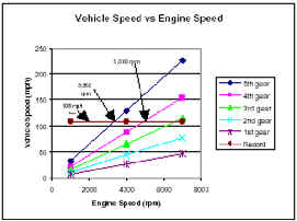
Figure 11 - Vehicle speed versus engine speed
In order to exceed the current record of 108.268 mph, the
vehicle would need an engine speed of more than 5,000 rpm, if the transmission
is in 4th gear, or an engine speed of more than 3,350 rpm if the transmission
is in 5 th gear. As can be seen in Figure 10, the engine will produce 172 HP
at 3,350 rpm and 253 HP at 5,000 rpm. Both of these power levels are well
beyond the estimated power level, of 140 HP, needed to propel the vehicle at
speed faster than the current record speed of 108.268 MPH.
Ignition System
The engine came with a Mallory Magnetic Breakerless
distributor that uses mechanical weights for timing advance (maximum of 32
degrees). This system is mechanically linked to the engine through a gear on
the camshaft. Each time the camshaft completes one revolution the rotor of the
distributor also makes one revolution. On the same shaft as the rotor are 8
vanes, one for each cylinder (see Figure 12).
Figure 12 - View distributor vanes
Each time one of these vanes pass by the magnetic pick up
sensor on the distributor, the coil (single) discharges, sending a high
voltage signal through the coil wire to the distributor. This signal would
then be distributed to the proper cylinder via the rotor, rotor cap and spark
plug wire. This type of ignition system works well for engines that do not
have an Engine Control Computer (ECC). However, for this project an ECC was
used and therefore another method for ignition timing was employed.
Engine Control Computer (ECC)
A programmable engine control computer (ECC) was utilized
to control fuel (sequential injection) and ignition timing. For the ECC to
accurately control these two parameters, it needs to know when a piston
(typically piston number one) is at TDC and if it is at TDC of its intake
stroke or TDC of its power stroke. To do this, two sensors were used: one on
the crankshaft (REF) and one on the camshaft (SYNC). For the REF signal, a
Ford 36 minus one tooth gear was installed, along with a Variable Reluctance
Sensor (VRS). Each tooth, and corresponding blank space, of the gear generates
one complete sine wave as it passes the VRS sensor. Each sine wave represents
10 degrees of crank rotation. Each time the missing tooth appears at the VRS
sensor (once every 360 degrees of crank rotation), the sine wave is altered as
shown in Figure 13. This altered sine wave indicates to the ECC that the
reference piston is at TDC. This however is not enough information to initiate
the fuel and ignition events for sequential injection. The ECC still needs to
know what cycle (intake stroke or power stroke) the piston is on. For this
information, a camshaft position sensor is needed to provide the SYNC signal.
Modifying the Distributor to Provide a SYNC Signal
For this project it was determined that the easiest way to
generate a SYNC signal would to be to modify the existing Mallory distributor
as opposed to mounting a sensor directly on the camshaft. As mentioned
earlier, the Mallory system uses 8 vanes on the distributor shaft to reference
the compression stroke of each cylinder (using a magnetic pickup sensor).
Removing 7 of these 8 (see Figures 14 and 15) vanes would in essence provide a
SYNC signal for the compression stroke of the reference piston (again, piston
number 1). The output signal from this system is a square wave.
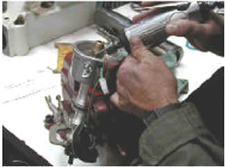
Figure 14 – Grinding out 7 of the 8 vanes.
Figure 15 – View of Distributor with missing vane
Using the two methods described above to determine the SYNC
and REF signal, the ECC is now able to accurately determine when piston number
1 is approaching TDC of its compression stroke and thus time the opening of
the fuel injectors and spark ignition. Transmitting the electrical current to
the spark plug can be done numerous ways. The preferred way would be to use a
“coil and plug” for each cylinder. This method however is fairly expensive
and not necessary for this project. A simpler and less expensive method was
used for this project. This method utilized the existing distributor system
(rotor, cap, wires, etc) to transmit the current to each of the spark plugs
(similar to the original system. The main difference with the new system is
that ignition advance is controlled directly by the ECC and not by centrifugal
weights in the distributor.
Task 6
The October meet at the Bonneville Salt Flats was cancelled due to rain and
therefore no record run was attempted. A record attempt is planned for the
next meet in August of 2002.
DISCUSSION
The design approach for this project was heavily influenced by budget and
time constraints. Therefore, not all the design decisions were based on the
best option available, but the best option that would work within our
constraints. The vehicle described in this report was successfully designed
and built under the given time and budget constraints. Whether or not it has
met the design goal of this project, that is, setting a new land speed record
for hydrogen powered vehicles will be made clear at the next event.
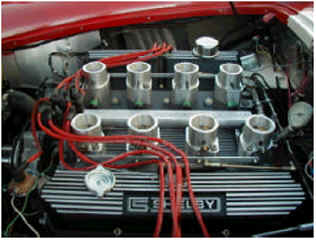
Figure 16 – View of Engine Converted to Run on Hydrogen
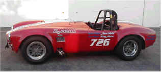
Figure 17 – View of Cobra. Painted and ready to go.
ACKNOWLEDGEMENTS
The authors would like to thank the following
organizations/people that have provided help and/or funding for this project:
Shelby American, Inc., Cal-Draulics, SunLine, IMPCO, KWJ
Engineering ,Circle Seal Controls, Clean Air Now! (CAN!), K & N Filters,
Ben Jordan, Bob and Dolores Zweig, Tony Avila, Anthony Avila, Herman Broom,
Douglas Kruse, Paul Shepherd, Mike Guidry, Larry Dashield (College of the
Desert), Bob Marsh, Tom D’antonio, Gary Davis, Deena Heffel, Jeanette
Johnson
GLOSSARY
1. FE engine. The FE designation refers to
passenger-car
and light-truck big block engines built by Ford from
1958 to 1971.
2. Side-oiler. A side-oiler engine has an oil gallery
along
the left side of the block that feeds the main bearings
before the cam bearings.
3. HiPo engine. Engine designation for High
Performance.
REFERENCES:
1. Norbeck, J.M.; Heffel, J.W.; Belinski, S.E.;
Durbin,
T.; Bowden, J.P. Tabbara, B.; and Montano, M. (1996)
Hydrogen Fuel for Surface Transportation. Society of
Automotive Engineers, Warrendale, PA.
2. Heffel, J.W., and Norbeck, J.M. (1996) Evaluation of Supercharged
Hydrogen Fueled Ford Ranger
Trucks. CE-CERT Technical
Report 95:AV:043F.
3. Heffel, J.W., and Norbeck, J.M. (1995) Evaluation of UC Riverside’s
Hydrogen Powered Truck. Proc. Of the 6th Annual National Hydrogen Association
Meeting, Alexandria, VA, March, pp. 85-111.
4. Gabbard, A., (1988) Fast Fords. HP Books.
5. Ricardo, H., The High-Speed Internal Combustion Engine, Blackie and Son,
London, 1960.
Jim Heffel is principal
engineer for the University of California Riverside CE-CERT
hydrogen research program. He has published many papers on hydrogen
applications and was a key contributor to a fuel cell engine training manual
coordinated by College of the Desert. The manual will be used by A/C Transit
of Oakland California to familiarize their technicians on the properties of
hydrogen and it’s use in fuel cell busses.
Jim
continues refining the Shelby Cobra for another attempt at the land speed
record for an alternative fuel vehicle.
For more information see www.cert.ucr.edu
